Emissions and Tier Ratings
The diesel engine has been a vital workhorse for many industries around the world, powering large trucks, farm equipment, recreational vehicles, railroad equipment, marine vessels, construction, and mining fleets. Diesel engine exhausts do, however, contain harmful pollutants in a complex mixture of emission gases and particulates, which are known to be harmful to the environment and humans. These emissions include:
- Oxides of Nitrogen (NOx) — Gases that form when diesel fuel is burned with excess air.
- Diesel Particulate Matter (DPM) — Microscopic solid particles and liquids that form during the combustion process.
- Hydrocarbons (HC) — Gaseous compounds that result from unburned fuel and lubricating oil.
- Carbon Monoxide (CO) — Colorless, odorless gas produced when hydrocarbons in diesel fuel are not burned completely.
Contrary to popular belief, diesel engines only emit a small amount of Hydrocarbon (HC) and Carbon monoxide (CO), so engine manufacturers primarily focus on reducing NOx and DPM. These two types of emissions are inversely related; meaning a reduction in one generally causes an increase in the other. Such a relationship complicates the management of them.
Regulations
The movement towards reducing diesel emissions began in the 1970s & 80s with the USA EPA investigating engine gaseous emissions from the heavy-duty highway diesel engines. The regulation of harmful exhaust emissions began in 2000 when the levels of NOx and DPM began to be controlled under a “tiered” series of emissions regulations which mandated a maximum level. A huge step forward was taken in 2000 when standards issued by the USA EPA directed very large reductions in exhaust emissions for model year 2007 heavy-duty engines. These tiered structures now govern new static and off-road engines and equipment, and establish progressively lower allowable emissions of NOx and DPM.
Each progression of standard level (Tier 1, Tier 2, Tier 3 and Tier 4) required engines to produce lower emissions, and necessitated more advanced technology than the previous generation. Essentially, the standards require that manufacturers reduce the levels of DPM and NOx in four steps, resulting in 96% lower levels than the levels produced by diesel engines that were available in the late 1990s. It is important to note that today’s Tier 4 emission requirements apply to new products only and do not apply retroactively to any engines or equipment manufactured prior to 2006.
High Pressure Common Rail Fuel Injection Technology
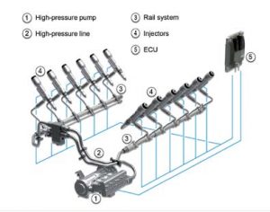
High Pressure Common
Rail
Fuel Injection
The pressure for injection is developed by the high-pressure fuel pump (1), which is mechanically operated by the engine. A common fuel rail (3) connects each injector from the fuel pump; hence where the terminology of Common Rail originated. The design of this system is such that a constant fuel pressure is available at the injector 100% of the time during engine operation thus providing a higher available mean time injection pressure over EUI designs. This feature ensures that fuel droplets are atomized the moment they leave the injector nozzle. As EUI systems must develop the fuel pressure during the injection event, they have a tendency to form larger droplets at the start and end of each injection event. HPCR injection systems are also able to regulate fuel injection pressure based on engine requirements, speed, and duty using the engine ECU combined with the fuel pump.
The modern HPCR fuel injector is unlike its EUI predecessor, and to understand why they are more susceptible to contamination related problems is important to appreciate how they function during engine operation. Unlike EUI systems, which typically inject fuel once or twice per engine revolution, HPCR fuel injectors can provide up to 5 injection events per single compression stroke of the engine.
Putting this into perspective, with a large high-speed diesel engine operating at 1400 RPM, the fuel injector is capable of injecting fuel into the combustion chamber in varying quantities depending on the ECU outputs, up to 1,750 times per minute, or 29 times per second with the fuel exiting the injector tip at speeds in excess of 700 miles per hour.
Diesel Fuel Quality
Poor quality or contaminated diesel fuel contributes to more than 80% of fuel system related failures in EUI engines and an even greater amount in HPCR systems. In order to overcome the challenges of operating a reliable fuel system, a paradigm shift must be made in the way consumers view the diesel fuel and its function within the engine.
Historically, consumers of diesel fuel have generally purchased, stored, and distributed the fuel to machines, engines or marine vessels as required with little thought put into fuel contamination control. Over the past 60 years, little has changed in the way many diesel engine owners and operators have undertaken this process. However, with the introduction of these new engines with advanced fuel injection systems, many users are experiencing a high frequency of failures, decreased availability, and increased downtime, as well as cost challenges from a technology that promised to improve operational profitability.
Along with the introduction of HPCR injection systems, we are now starting to see a parallel increase in diesel fuel related problems within many industries including Power Generation, Marine, Agriculture, and Mining. The most common complaint is that the new engine (using HPCR injection systems) simply do not last as long as older engines did (EUI Injection). These issues initially created a storm of confusion with fuel suppliers, fuel additive suppliers, filter manufacturers, fuel purification companies, and engine OEM’s, all who seemed to have their own opinions or in some cases, magical solutions to offer. Little, however, has been done to educate the end user or provide them with real technical information in relation to the root cause of the problems. Most users are now finding that they are treating the symptoms of these failures rather than actually treating the root cause of them.
Diesel engines are used in a wide variety of applications around the world and with some, they can literally mean life or death or perhaps millions in lost revenue. Such engines are typically found in Mission Critical applications such as data collection or data back-up facilities, hospitals, first responders, and the military. With diesel fuel directly contributing to greater than 80% of fuel system failures, it is imperative that these diesel engine users dramatically alter the way in which they view and treat the diesel fuel they consume, from simply seeing it as a commodity or a necessary expense, to that of a “Critical Reliability Component” of the fuel system, the engine, and the overall asset or facility. The cost through poor management of the engine injector system is far too great.
How Fuel Cleanliness Impacts Engine Operation
Poor quality or contaminated diesel fuel contributes to more than 80% of fuel system related failures in EUI engines and an even greater amount in HPCR systems. In order to overcome the challenges of operating a reliable fuel system, a paradigm shift must be made in the way consumers view the diesel fuel and its function within the engine.
Historically, consumers of diesel fuel have generally purchased, stored, and distributed the fuel to machines, engines or marine vessels as required with little thought put into contamination control. Over the past 60 years, little has changed in the way many diesel engine owners and operators have undertaken this process. However, with the introduction of these new engines with advanced fuel injection systems, many users are experiencing a high frequency of failures, decreased availability, and increased downtime, as well as cost challenges from a technology that promised to improve operational profitability.
Along with the introduction of HPCR injection systems, we are now starting to see a parallel increase in diesel fuel related problems within many industries including Power Generation, Marine, Agriculture, and Mining. The most common complaint is that the new engine (using HPCR injection systems) simply do not last as long as older engines did (EUI Injection). These issues have created a storm of confusion with fuel suppliers, fuel additive suppliers, filter manufacturers, fuel purification companies, and engine OEM’s, all who seem to have their own opinions or in some cases, magical solutions to offer. Little, however, has been done to educate the end user or provide them with real technical information in relation to the root cause of the problems. Most users are now finding that they are treating the symptoms of these failures rather than actually treating the root cause of them.
Diesel engines are used in a wide variety of applications around the world and with some, they can literally mean life or death or perhaps millions in lost revenue. Such engines are typically found in Mission Critical applications such as data collection or data back-up facilities, hospitals, and the military. With diesel fuel directly contributing to greater than 80% of fuel system failures, it is imperative that these diesel engine users dramatically alter the way in which they view and treat the diesel fuel they consume, from simply seeing it as a commodity or a necessary expense, to that of a “Critical Reliability Component” of the fuel system, the engine, and the overall asset or facility. The cost through poor management of the engine injector system is far too great.
In today’s world, measuring how clean or dirty fuel may be is critically important, and as such, fuel cleanliness levels are now measured and reported according to the ISO Cleanliness Code 4406:1999. The International Organization for Standardization (ISO) created the cleanliness code ISO4406:1999 to quantify particulate contamination levels per milliliter of fluid at three sizes: 4μ, 6μ, 14μ.
Scale
Number
Particles
per ML:
More Than:
Particles
per ML:
Less Than
or
Equal
to:
22
20,000
40,000
21
10,000
20,000
20
5,000
10,000
19
2,500
5,000
18
1,300
2,500
17
640
1,300
16
320
640
15
160
320
14
80
160
13
40
80
12
20
40
11
10
20
10
5
10
9
2.5
5
8
1.3
2.5
7
.64
1.3
6
.32
.64
Worldwide Fuel Charter Fuel Cleanliness Standards
Fuel cleanliness levels using the ISO4406:1999 method were officially documented as a global standard in 1998 with the development of the Worldwide Fuels Charter (WWFC). Since its inception, the charter has established a minimum cleanliness level for each of the diesel fuels under various available categories around the world. A copy of the Fifth Edition of the Worldwide Fuel Charter dated September, 2013, may be viewed in .pdf format here.
WWFC Diesel Category Fuel Cleanliness Standards
Diesel
Category
Cleanliness
Level
1
10 mg/kg
2
ISO 18/16/13
3
ISO 18/16/13
4
ISO 18/16/13
5
ISO 18/16/13
Most mainstream engine OEM’s now subscribe to these standards. Interestingly, however, and somewhat troubling to note, is that fuel cleanliness levels for each Diesel Category being specified by engine OEM’s and the WWFC have not changed since their inception in 1998. Despite the enormous advances in fuel injection technology, and the demands under which HPCR Fuel Injection systems operate, increasing the fuel cleanliness requirements is needed to assure optimal performance and longevity of system components. The following table shows how the characteristics of the more advanced HPCR systems have changed.
Diesel Fuel Injection – Advancing Technologies & Cleanliness Levels
Injection
EUI
HPCR
Pressure1
16,000 psi
36,000 psi
Viscosity
1-4 cSt
1-4 cSt
Clearances
5-8 micron
1-4 micron
Cleanliness
ISO 18/16/13
ISO 18/16/13
This table shows that fuel injector critical clearances have halved and fuel pressures have doubled yet the level of fuel cleanliness being specified has not been altered in accordance with such advancements. In fact, the same cleanliness levels specified in 2000 are still being used today despite these magnificent technological advancements.
Leading fuel injector manufacturers around the world have clearly identified and communicated that their systems require Ultra Clean Diesel (UCD) fuels with fuel cleanliness levels as low as ISO 12/9/6 to maintain ultimate performance and reliability while fuel being provided is ISO 18/16/13. It is here where we see an enormous mismatch in what the fuel injection OEM desires as a fuel cleanliness level, to what the engine OEM’s and the WWFC are advising the industry. The following table identifies the discrepancies in fuel cleanliness levels.
Diesel Cleanliness Levels
Company
Specified ISO
Cleanliness Level
World Wide Fuel Charter
ISO 18/16/13
Engine OEMs
ISO 18/16/13
Fuel Injector OEMs
ISO 12/9/6
Owners and operators of diesel engines should take note that the cleanliness levels required by the fuel injector OEM’s are 64x cleaner than what the industry is being advised as an acceptable standard of fuel for engines. This is a critical point when considering contamination control solutions for diesel fuel systems.
When referring to the ISO4406:1999 cleanliness code, it can sometimes be difficult to comprehend how much contamination the codes actually represent in a real world operating system. To help clarify this, we can use a real world scenario that is more meaningful. The example used to demonstrate this is as follows:
Model:
Cummins DQKB Diesel Generator
Engine:
QSK60-G3
Duty:
Continuous
Rating
1450kW
(1813kVA)
Cycle:
60Hz
Load:
100% Peek
Load
Run Time:
5000
hrs/year
Fuel:
74.8 US GPH
(283 L/hr)
The following table provides an indication of how much contamination is being presented to the above engine’s fuel system each year under this example.
Volume of Contamination
Fuel
Cleanliness
Volume of
Contamination
ISO 23/21/18
26.4 lb/year
ISO 18/16/13
0.8 lb/year
ISO 12/9/6
0.10 lb/year
Diesel Fuel Contaminants
All contaminants found within diesel fuels are detrimental to both the engine and the fuel itself, and there are many types of contaminants.
Contrary to popular belief, water is the most damaging contaminant found within diesel fuel and is a primary catalyst to additional fuel breakdown and the formation of other contaminants. Water can be present in diesel in dissolved, emulsified, and free states.
Water has many detrimental effects to the fuel. Dissolved water, for instance, can affect fuel stability, while water in its free and emulsified states can be more problematic to the engine fuel system. Not only can water cause damage to the fuel system, including the sensitive fuel injectors, it also promotes microbial growth within a fuel tank. When enough water is present, being that it is heavier than diesel, it will fall to the bottom of a fuel tank where additional acids can be formed, causing damage to tank walls and bottoms. A layer also forms between the diesel and free water boundary and this is where microbial contaminants will grow, feeding off the hydrocarbon, but living within the water.
Dissolved Water
Diesel Fuel
Dissolved Water
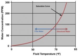
All diesel fuels have the ability to retain water within the fuel in a dissolved state. The ability of the fuel to hold the water in a dissolved state is highly dependent on the temperature of the fuel and its overall condition. Much like a mug of hot coffee can retain a certain volume of sugar dissolved within the water, it is the same for water in fuel. Taking the mug of hot coffee and sugar as an example, the coffee will dissolve the sugar and hold it chemically within the water while it remains hot. Sugar can continue to be added and dissolved, but at some stage the hot coffee will be saturated with sugar and no longer be able to hold any more within solution. At this point, sugar will start to collect at the bottom of the mug, instead of dissolving into the coffee. This is what is known as the Saturation Point. Additionally, as the mug of coffee cools down over time, more and more sugar will fall out of solution and down to the bottom of the mug. This phenomenon is identical to that with water contamination in diesel fuel.
All diesel fuels have the ability to retain water in a dissolved state up to a certain volume. With most #2 diesel fuels found around the world, it is typically around 140-240ppm (0.014 – 0.024% by volume). In fact, many of the world’s diesel engine OEM’s clearly specify that water contamination must remain below 200ppm to ensure the reliable operation of the fuel injection system. The graph above illustrates a typical saturation curve for a diesel fuel. As can be seen, the ability for the fuel to retain water in a dissolved state is highly dependent on temperature.
Emulsified Water

Water Emulsified into Fuel
This is the state whereby microscopic water droplets have fallen out of a dissolved state and, due to the turbulence and the mixing effects within an operating diesel system, the water becomes emulsified and is unable to fall away and to the bottom of the tank. The images to the left show diesel fuel with water contamination in an emulsified state. Note that the water contamination within the examples have been dyed blue to provide a more clear representation of the 2 states.
Free Water
Free water is water that falls out of suspension in the fuel and gathers at the bottom of the fuel tank, as seen to the right. This can only occur once the diesel fuel has been saturated with water in a dissolved state and the temperature conditions are not high enough to hold additional water.

Free Water Separation
Diesel fuel that is found to be in a hazy condition is typically found to be contaminated with water to some degree held in a dissolved state. Diesel fuels should be continually monitored for water contamination levels whilst in storage and maintained at levels below 200ppm.
Microbial Growth
There is one simple rule when it comes to microbial growth in a diesel fuel tank; it cannot exist without the presence of water. Many fuel consumers, however, never actually treat the cause of the problem, but rather treat the symptom of the problem. There are literally thousands of products and brands on the market all offering their own unique benefits to remove and prevent microbial growth. The ONLY method, which actually guarantees the prevention of microbial growth, is to remove the catalyst (water) and prevent the contamination in the first place.
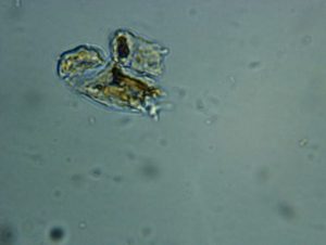
Microbes in Water Habitat
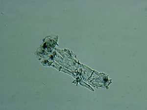
Microbes in Water Habitat
Dark Fuel
Asphaltenes are a bituminous material found in most diesel fuels with the concentration varying between batches and geographic location around the world. They are a natural contaminant from the refining process of producing various fuels out of a base crude oil. Asphaltenes are not soluble in fuel and are generally less than 2μm in size in their natural state. However, within diesel fuel they have a tendency to agglomerate, forming clusters in the order of 100-200μm, making them a key component to premature fuel filter blockage. Asphaltenes are NOT always filtered out by fuel producers in the refining process due to their small size and the expense of removal.
In some countries in Continental Africa and South America, emissions standards are less stringent and fuel sulfur levels are higher. In these locations, diesel sulfur levels remain at 500-5000ppm and there is some evidence to suggest that such fuels are manufactured with blends of light cycle oils from the refining process in order to use more from each barrel of crude oil. Fuels in these locations are generally black in color and contain large quantities of asphaltenes which makes the purification extremely challenging, and in many cases, very expensive.
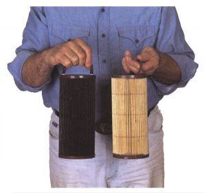
Fuel Filter Comparison
It is a fact that most filter elements in use for diesel fuel applications are changed often due to the effects of asphaltenes. Filter elements that are coated by a black, tar-like substance have typically been affected by asphaltene contamination as seen in the picture on the right.
Water and Particles
Water and particles are the two contaminants that cause the greatest damage within a diesel engine fuel system. Not only are they a primary contributor to failure, they are also the two sources for secondary failure points within an engine and degradation of the fuel.
Here are two classifications for the types of failure within a fuel injection system: Partial Functional Failure and Catastrophic Full Functional Failures. Partial Functional Failure can also be referred to as a performance failure. Catastrophic Failures are well understood and result in the fuel injector or engine ceasing to function.
Partial Functional Failure
Often, partial functional failure of an engine will go unnoticed until it is too late. Engine inefficiencies are seldom felt by a user, but can result in real world losses in revenue. A major reason for engine inefficiency can stem from partial failure of the engine’s fuel injection system, which is less well understood. Injector partial functional failure is rarely well documented and poorly investigated for use in formulated strategies to mitigate similar future events.
A partial functional failure within a fuel injection system is generally one that reduces the performance or efficiency of the injector and thus the overall performance or efficiency of the asset. The symptoms of such performance failures within an injection system may include the following:
Low power from the engine
Reduced engine RPM
Increased fuel consumption
Poor cycle times or low speed
Smoke
Lower gear selection
Noise
Poor starting
Poor idle
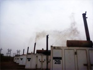
Many of the symptoms mentioned here are difficult to monitor accurately. An excellent example showing engines with various levels of fuel injector partial functional failure can be seen in the following images. The varying levels of smoke opacity, with engines running at the same RPM and load, is directly related to poor fuel combustion – with the fuel injectors being primarily at fault. The two engines closest to the right side of the photo show little or no smoke from the exhaust stack, while the engine closest to the middle of the photo shows a high degree of smoke (DPM – Diesel Particulate Matter) emanating from the engine.
Diesel Engine Failure
A diesel fuel injector’s performance, be it an electronically controlled unit injector (EUI) or high pressure common rail (HPCR), drops from its designed functionality the moment any of the designed tolerances within the injector alter, thus affecting the design of the fuel spray profile within the combustion chamber. The changes in these injector tolerances can occur through the erosive and abrasive effect that contamination plays on metal surfaces, the alteration in injector nozzle hole size, or the number of open holes. As further evidence of this, Robert Bosch, author of the book “Diesel Fuel Injection 1st Edition” wrote that “deviations of less than, or equal to, 2° from the optimum injection direction will lead to a measurable increase in black smoke emission & fuel consumption.”
Catastrophic Full Functional Failure
Catastrophic full functional failures are those that simply cause the engine to cease functioning. They are often dramatic events, highly visible to operations and high in cost and resulting downtime. It is for these reasons engineering, CM, and RE businesses typically focus their attention on monitoring, predicting, managing, and reducing such events. Additionally, hourly-based planned maintenance strategies are specifically designed around preventing such failures through known MTBF, advised by both OEM and industry specialists alike. An excellent example of this are the mandatory fuel injector replacements at half engine life (based on operating hours) that many OEM’s advise as part of their warranty or maintenance program. An obvious question should be raised here. If an engine is provided fuel at the OEM specified fuel cleanliness level, then why would the fuel injectors need to be replaced halfway through the life of the engine?
Clearly, OEM’s are aware that cleanliness levels such as ISO 18/16/13 do not provide the fuel injection system with a cleanliness level that will ensure its ultimate reliability, and it is for this reason that fuel injector change outs are recommended at engine half-life.
There are many types of common engine failures and most are typically well understood and managed by engineering and maintenance practitioners. However, there are some engine failures which can never be properly diagnosed, making it difficult for professionals to develop a suitable solution to the problem. Some of these more common engine failures can be misdiagnosed, and if correctly analyzed, attributed to failures within the fuel injection system.
High velocity and high-pressure fuel flow, with even the smallest amount of contamination, will gradually erode the sealing surfaces of the injector valve seat. Once valve wear has initiated, a chain reaction gradually occurs, resulting in a partial functional failure evolving into the full functional failure of the valve and the need for replacement.
The Failure Chain Reaction
Valve erosion initiates
Fuel leakage through the valve mating surfaces initiates
Localized hot spot generation through the leakage zone causes fuel oxidation
Reduced fuel pressure at nozzle
Reduced volume of fuel delivered. Engine management system compensates by increasing injection event time (more fuel).
Reduced fuel atomization
Soot generation within the cylinder
Increased emissions
Loss of power
Partial Functional Failure Point
Leakage rates continue to increase as wear continues
Fuel consumption increases as the engine controller unit tries to compensate for leakage
Visible and audible signs
Full Functional Failure Point
There are three principal locations inside a high pressure common rail fuel injector that suffer from the erosive and abrasive effects of contamination, resulting in a loss of functional efficiency. These are:
Fuel injector nozzle holes
Needle valve and seat
Electronic Peizo or solenoid controlled valve
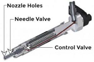
HPCR Fuel Injector Critical Zones
Nozzle
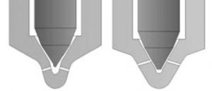
There are two predominant diesel fuel injector nozzle designs that are in circulation today: the area around pintel tip (SAC) (pictured on the left) and valve covered orifice (VCO) (pictured on the right) type nozzles. Modern HPCR fuel injectors typically utilize the VCO type as it completely covers the nozzle holes. This design enables the injector to abruptly and completely shut off the fuel at the end of an injection event, thus providing a more stringent control of the fuel injection event. The two designs can be seen below.
Fuel Injector Types
Due to its design, the VCO type needle valve has extremely fine tolerances and is highly susceptible to valve misalignment during rise and fall. Remembering that the rise and fall can occur 29 times per second at 1400 RPM in a large high-speed diesel engine, any misalignment, or changes in the tolerances within the valve, will give rise to variations in the flow area, the volumetric fuel passing through the various holes, and the atomization of the fuel – all of which effect the combustion of the fuel and fuel efficiency.
Nozzle Holes
Fuel injector nozzle holes generally have two failure conditions which result in a partial functional failure of a fuel injector. These two conditions are Blockage and Erosion. HPCR fuel injectors are finely tuned and balanced precision devices that are designed to inject a very fine fuel mist consisting of micro-fine droplets into the combustion chamber with millisecond precision timing. Fuel droplets burn from the outside in, and as such, it is important for the fuel injection system to maintain the consistency of the mist for correct and efficient combustion to take place. Modern HPCR fuel injection systems are specifically designed to reduce the droplet sizes of the fuel while increasing the number of injection events per engine cycle. When correct combustion takes place as designed by the injector manufacturer, the fuel droplets burn out completely before they reach the engine cylinder liner. Failure to complete combustion in this way results in the build up of soot within the engine which results in increases in nitrogen oxide (NOx), carbon monoxide (CO), and diesel particulate matter (DPM).
To maximize combustion efficiency and reduce emissions, modern HPCR fuel injectors typically have 5-8 very fine holes which are machined into the injector tip using a process called Electro Discharge Machining (EDM). These holes allow the fuel to exit the fuel injector and immediately atomize within the combustion chamber. The size of these holes will vary from manufacturer to manufacturer and depends on the size and application for each fuel injector. Hole sizes are typically 20μm-250μm.
The Fuel Injection
As a fuel injection event takes place, diesel fuel is sprayed into the combustion chamber, which unlike gasoline engines, is typically housed inside the piston crown. As the piston moves downwards in its power stroke, sprays from the injector protrude further into the volume of the combustion chamber. Fuel should be burnt out before any droplet reaches the cylinder walls. When, however, the spray pattern generated by the injector is not as designed, the fuel droplets become larger and therefore take longer to burn out. Soot generation, high DPM, and smoke are by-products of this problem. The soot generated within the combustion chamber gradually builds up on the injector tips, causing blockages to occur as well as accumulation within the exhaust system, the valves, and on cylinder walls where it is typically removed by the piston moving up and down and thus washed into the engine sump where it contaminates the engine oil. Excessive soot build up within engine lubrication oil is directly correlated to poor fuel injection or combustion.
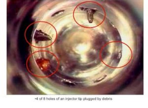
Blocked Fuel Injectors
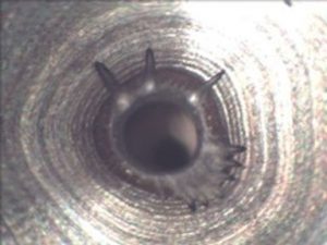
Injector Orifice Erosion

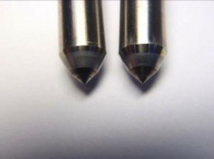
Clean Injector on left, soot accumulation on Injector on right
Fuel injectors that have one or more of the nozzle holes blocked due to contamination or soot build up will cause an increased fuel velocity through the open nozzle holes, thus reducing atomization. Micron sized contaminants can also gradually block some or all of the individual nozzle holes as a result of tight injector clearances and the electromagnetic conditions present inside. Nozzle holes that remain unblocked will see an increased flow rate, causing fuel to be ejected faster and increase the potential for wear.
The jetting of fuel (a continuous stream of fuel in a concentrated direction) within the cylinder can eventually result in the engine lubricating oil to be washed from the side of a piston and cylinder if left unchecked. This loss in lubrication film can result in the development of a hot spot and uneven thermal expansion of the piston, potentially causing the eventual piston seizure to the cylinder sleeve, resulting in a catastrophic failure. Interestingly, such failures are commonly categorized as lubrication failures and not the result of poor fuel injection. In March 2004, staff members of the Department of Mechanical, Aeronautical & Chemical Engineering at the University of Pretoria South Africa delivered a paper at the International Conference of the South African Institute of Tribology, which provided hard evidence of such failures.
The common approach to rectify the build up of soot or contamination within the injector is to seek out and use diesel fuel additives that are designed to clean soot from the injector tip and internal deposits. While this can be an effective means of cleaning the injector, in most cases the problem continues, as the root cause of the problem (contaminated fuel and worn injectors) has not been corrected. Again, it must be stressed that the build up of contamination and soot is a symptom of a far greater problem that should be corrected as a first step.
Needle Valve
Contaminants in diesel fuel also have an erosive effect on the needle valve within the injector. This valve is designed to seal off the fuel within the injector following an injection event. Poor sealing of the valve can result in the fuel injector dripping fuel into the cylinder and onto the piston crown. This problem is more predominant within HPCR fuel systems with the fuel injector being pressurized 100% of the time. Such problems were less evident with EUI systems where full fuel injection pressure only exists for 5% of the engine run time. The image below provides two examples of fuel injector needle valves from an EUI SAC type fuel injector tip. The valve on the left failed within 1000 hours of operation in an Allen diesel engine used for power generation. The valve on the right is shown as evidence of a near new condition (100hrs), although some scratches are shown as evidence of the contaminated fuel this facility was faced with.
Worn Injector and New Injector
Dripping fuel injectors can cause a multitude of problems and catastrophic failures. The predominant failures caused by dripping fuel injectors are excessive piston crown temperatures causing the crown to deform or melt, resulting in engine failure.
Control Valve
All electronic controlled fuel injectors, either EUI or HPCR, incorporate a control valve that is used to control the timing of each fuel injection event. In EUI type fuel injectors, the valve is controlled via an electronic solenoid. Most new HPCR injectors are controlled via a Piezoelectric actuated valve, which enables far greater control of valve movement (distance) and a far greater control of speed. No matter how the valve is actuated, it is by far the most critical component and the most sensitive to contamination. In most applications where HPCR fuel injectors are employed, the control valve inside the injector only opens a distance of approximately 20-30μm. When open, high-pressure fuel up to 40,000 psi travels over the metal sealing surfaces at speeds faster than a jet airplane. Extremely fine contaminants suspended within the fuel gradually erode and damage the sealing surfaces and the fine-machined tolerances.
Additional problems occur within the control valves when ultra-fine contaminants below 4μm, enter the critical clearances between the valve pintle and the valve body. The trapped silt within the clearance zone restricts the movement of the pintle, which results in sluggish movement of the valve, poor injection timing and eventual seizure. Such seizures typically result in the solenoid coil or the Peizo failing or a fault signal within the ECM. These failures are almost always classified as electrical faults by either manual detection or the ECM, when in fact it is contamination that has initiated the problem.
High velocity and high-pressure fuel flow, with even the smallest amount of contamination, will gradually erode the sealing surfaces of the injector valve seat. Once valve wear has initiated, a chain reaction gradually occurs, resulting in a partial functional failure evolving into the full functional failure of the valve and the need for replacement.
Diesel Filters
It is a common belief that the engine fuel filter, installed by the engine manufacturer, will provide the required level of contamination protection in order to achieve reliable operation. This is a fair and reasonable assumption because the intended function of a diesel engine fuel filter is to “achieve a fuel cleanliness that will enable the fuel injection components to function reliably and within their designed operating parameters throughout the life of the component.” However, there are several key aspects regarding the application of engine fuel filters that call into serious doubt in their ability to achieve this result or the more stringent cleanliness level being sought by HPCR fuel injector manufacturers.
Most major engine manufacturers have determined that fuel must meet or exceed a cleanliness level of ISO 18/16/13. The Worldwide Fuel Charter (WWFC) also supports this. It is therefore fair and reasonable to assume that the engine fuel filter needs to improve in order to achieve the injector OEM required cleanliness levels of ISO 12/9/6.
A typical passive diesel fuel filtration system installed on a HPCR injected engine uses both a primary filter and secondary filter to achieve the desired cleanliness level. The primary filter is typically installed on the suction side of the low-pressure fuel pump, with the secondary filter on the pressure side. Again, manufacturers will modify these designs depending on requirements of the engine and their research into what they believe works best.
Synthetic Welaid Microglass
Filter Media
The primary filter is generally required to remove larger particles that can damage the low-pressure pump and also separate undissolved water from the fuel. The secondary filter is generally designed to remove the smaller particles, those larger than around 4 micron, which are known to damage the downstream engine components such as the high-pressure fuel pump and the fuel injectors.
Two-stage systems sometimes use a coalescing or silicon treated filter for water removal and a surface filter for particle removal. The two-stage system typically utilizes media derived from cellulose or a cellulose/glass composite. The secondary filter can be a finer cellulose composite media, or in the most advanced systems now being used on HPCR injection systems, a fully synthetic glass fiber filter media.
Some new filter designs use a single-stage system that incorporates the water removal capability of the primary filter with the high efficiency particle removal of the secondary filter. Single-stage systems typically use a single filter with a multilayer composite structure.
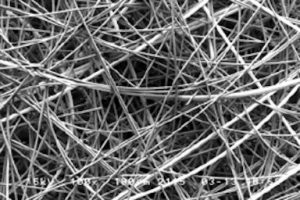
The current state-of-the-art filter designs now use a melt blown glass media formed on or laminated to, a nanofiber substrate support and typically bonded with a Phenolic or Epoxy resin.
Conclusions
As engine and fuel injection technology changes at a rapid pace, so are the challenges of maintaining supreme reliability and longevity of a diesel engine and its fuel system. New HPCR fuel injection systems require a vast improvement in fuel cleanliness levels in order to maintain this high degree of reliability and as such, advancements must be made in the way operators deal with the ever-growing problem that fuel contamination brings.
The reliance on the engine fuel filter to perform the entire function of fuel cleanliness control can no longer be accepted. Certainly the filtration technology used in today’s engine fuel filters has improved. However, the physical size of filters has changed little to offset reduced filter life. Often the filter is used that cross references to the application while being available at a reduced cost, but does not achieve the level of filtration needed to meet the engine manufacturers requirements, let alone those of the HPCR equipment manufacturer.
In addition, the problems of vibration and flow surges have not been addressed by filter manufacturers. Operators of diesel engines must now look towards alternative solutions by using contamination control technologies throughout the diesel distribution and storage system that is under their control. This can help to reduce contamination levels so that the engine fuel filter can perform its design function which is to achieve a fuel cleanliness that will enable the fuel injection components to function reliably and within their designed operating parameters throughout the projected life of the component.
Just as the medical profession utilizes specialist practitioners to treat special or difficult medical conditions, so too does diesel fuel contamination control require a specialist. Choosing solutions (treatments) because they present the lowest cost will never provide an economically viable solution and in many cases can actually make matters worse. Contamination control solutions for diesel distribution and storage systems under the control of the operator of diesel engines should only be designed by experienced practitioners who understand the complexities surrounding them and the benefits that can be obtained following the improvements. Such professionals are able to call upon the most recent technologies and advancements in design, along with experience to bring them into practice, for each new application or system.
References
ACEA, AAM, EMA, and JAMA, Worldwide Fuel Charter, 4th edition, September 2006.
ISO 4406:1999 Hydraulic fluid power – Code for defining the level of contamination of solid particles.
ISO 16889 Hydraulic fluid power — Filters — Multipass method for evaluating filtration performance of a filter element, 1999
ISO 19438:2003 Diesel fuel and petrol filters for internal combustion engines – Filtration efficiency using particle counting and contaminant retention capacity
ISO/TS 13353:2002 Diesel fuel and petrol filters for internal combustion engines – Initial efficiency by particle counting
ISO CD/23669 – 2005, Hydraulic fluid power filters – Multipass method of evaluating filtration performance of a filter element under cyclic flow conditions
ISO4020 – Road Vehicles – Fuel Filters for Diesel Engines
JIS D1617 – Automotive Parts – Fuel Filters for Diesel Engines Test Methods
SAE J905 – Fuel Filter Test Methods Section 4: Filter Capacity & Contaminant Removal Characteristics.
SAE J1985 – Fuel Filters – Initial Single Pass Efficiency Test Method
Caterpillar Ultra High Efficiency Filters PEHJ0269
Barry Verdegan, Abby True-Dahl, William Haberkamp, Norm Blizard, David Genter, and Eric Quillen, Cummins Filtration Inc, Cummins Inc., “Filtration Solutions for HPCR Systems”
Bosch Diesel Systems Technical Customer Document 0 449 D05 006 – Common Rail – Characteristic data Sheet
Lydall Filtration and Separation – “Design and Performance of Diesel Fuel Filters”, 7th International Filtration Conference
Glossary
CM – Condition Monitoring
CO – Carbon Monoxide
CO2 – Carbon Dioxide
DEF – Diesel Exhaust Fluid
DPM – Diesel Particulate Matter
ECU – Engine Control Unit
EMD – Electro-Motive Diesel
EPA – Environmental Protection Agency
EUI – Electronic Unit Injector
HC – Hydrocarbons
HPCR – High Pressure Common Rail
ISO – International Organization for Standardization
MARC – Maintenance & Repair Contract
MCRS – Modular Common Rail System
MTBF – Mean Time Between Failures
NOX – Oxides of Nitrogen
PM – Planned Maintenance
RE – Reliability Engineering
ROIC – Return on Invested Capital
SAC – “Sack” area around the pintle tip
SAE – Society of Automotive Engineers
UCD – Ultra-Clean Diesel
ULSD – Ultra Low Sulfur Diesel
UREA – Active ingredient in DEF made from synthetic ammonia and carbon dioxide
VCO – Valve Covered Orifice
WWFC – World Wide Fuel Charter