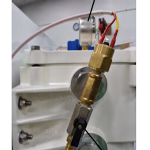
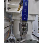
Configuration of Manual Additive Injection System components may change location and orientation depending on which system they are configured on.
Add Fuel Additive to your Storage Tank While You Polish Your Fuel
Most of the time it is easy to add AFC Series Fuel Additives, or other additives, to your fuel tank by simply using an access at the top of the tank and pouring it in. But large tanks require more additive that must be carried to the tank access, sometimes only accessable via a ladder, making carrying the additive while climbing the ladder a bit of a challenge. At times, accessing the tank at the top in wet weather conditions mean risking water entering the tank and personnel working in harsh conditions.
If only there was another way….
Now you can simply measure the amount of additive needed to treat the tank, attach a hose, and have your Fuel Polishing System add it as the fuel is circulating through your Fuel Polishing System.
Manual Operation:
With Automated Fuel Polishing System running, place hose from injection port into additive holding container. Ensure sufficient additive within holding container and that hose reaches bottom of additive container.
Open Additive Injection Ball Valve to inject additive.
To start, or increase, flow of additive into the Automated Fuel Polishing System, slowly close the Automated Fuel Polishing. System Main Ball valve creating a higher system vacuum (shown on vacuum gauge). Monitor pre-filter vacuum gauge, ensuring not to create a higher vacuum than the system set point (15inHG).
Monitor additive level in holding container for proper dosing level (with AXI AFC additives, overtreatment does not cause issues).
After additive injection is complete, close Additive Injection Ball Valve and close/properly dispose of additive holding container.
Return Automated Fuel Polishing System Main Ball Valve to its fully open position.
Depending on the vertical and horizontal distance between the additive holding container and the Automated Fuel Polishing system, operation may vary.
Manual Additive Injection System works with liquid additive only. Other types of fuel additive (other than AXI AFC products), should be cleared for proper operation with AXI International before use.
The Manual Additive Injection System is available as an option on the following systems: